Over several decades, processors and complex ICs have followed Moore’s Law to increase transistor count. However, the associated voltage regulators have not reduced in the same proportion until recently.
A new generation of devices that have adopted ‘3D packaging’ techniques is showing dramatic improvements in power density.
Moore’s Law
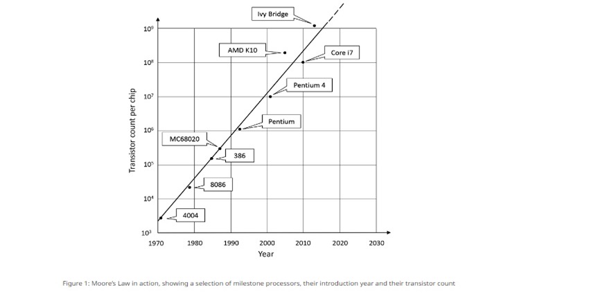
Moore’s Law, or more correctly his prediction, was that the number of transistors in a complex IC would approximately double every year. Gordon Moore made this statement in a popular magazine in 1965 and was only looking ahead ten years at the time.
He predicted that, from around 50 components in an IC in that year, by 1975 there could be 65,000 on a 6 x 6mm die. His prediction came close, with the Intel 8086 released in 1976 featuring 29,000 transistors using a process scale of 3.2µm. Moore then revised his estimate to doubling every two years.
Process innovations
Although the rate of increase in complexity has slowed, a scale of 2nm is targeted by TSMC for 2025, an amazing reduction in die feature size by a factor of 1600. As of 2022, the highest transistor count in a commercially available microprocessor is 114 billion, in Apple’s ARM-based dual-die M1 Ultra system, fabricated in a 5nm process.
This ‘System on a Chip’ consists of two dies, each 420mm2 in area. Process innovations such as 3D transistors and ‘die stacking’ have kept the metric of processing power per mm2 footprint on a similar exponential trajectory.
Power draw has not increased in line with the complexity
Power levels have still increased from around 1W for the Intel 4004 to 150W or higher for the latest parts
Power required for processors and SoCs has not increased in the same proportion to transistor count, as there is a reduction in device capacitances as transistor size decreases. This leads to lower dynamic losses and lower current draw. The size reduction has also led to the adoption of lower voltage supply rails to avoid breakdown. This has also contributed to lower power consumption.
However, power levels have still increased from around 1W for the Intel 4004 to 150W or higher for the latest parts, and the current drawn has increased from 67mA to around 150A, a factor of 2200.
150W DC/DC converter
The dramatic increase in current requires the necessary voltage regulators to be fitted very close to the processor to avoid excessive voltage drops and to provide the high peak currents demanded, which is a challenge for power designers.
When Moore wrote his article in 1965, a 150W DC/DC converter would have been the size and weight of a brick, and, even with the newly invented switched-mode power-conversion technique, losses would have been high.
Processors and complex ICs
Efficiencies have improved over time with techniques such as synchronous rectification and with better semiconductors, but a high-power DC/DC ‘Point of Load’ (PoL) converter was embarrassingly large until recently.
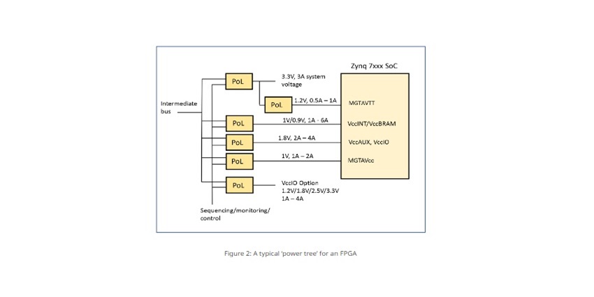
Module manufacturers typically resorted to vertical ‘SIP’ and inconvenient through-hole formats to preserve board space at the expense of height and disruption to airflow. Processors and complex ICs such as ASICs and FPGAs also need multiple voltage rails but usually at lower power. For example, the Zynq 7000 FPGA from Xilinx needs five rails, ranging typically from 1V to 3.3V (Figure 2).
PoL converter topologies have not changed
The benefit has not followed Moore’s Law though, and power converters remain a major proportion of board space used
In principle, conversion topologies used in PoL converters have changed little over several decades. Buck, boost and buck-boost circuits are used, which still use a semiconductor switch, diode or synchronous rectifier, inductor, and capacitor, with pulse width or frequency modulation to achieve regulation. Switches have evolved to exhibit lower static and dynamic losses and operate at higher frequencies, and inductor core materials have improved incrementally for lower loss, as have capacitors.
As a result, efficiency has increased, and this in turn has enabled better power density – PoL converters can be smaller for the same load and temperature rise. The benefit has not followed Moore’s Law though, and power converters remain a major proportion of board space used.
discrete components
Part of the problem with the size of the PoL converter is that discrete components have been traditionally used on a substrate with little integration. This follows from the simple fact that they are power converters and inevitably dissipate heat, so large components have been necessary to keep temperature rises low.
Also, the inductor and its core are difficult to fabricate as other than a bulky discrete component, and ferrite core technology has only improved in small steps over the decades.
switching frequency
Unlike processors, scaling down PoL converters in size tends to directly introduce thermal problems
This means that a minimum number of coil turns is necessary, which must also be thick enough to withstand the higher currents without overheating. This makes for a bulky component.
The number of turns required decreases as the switching frequency rises for the same core flux density and output ripple current, but then core and PoL converter switching losses increase, requiring a larger PoL anyway to dissipate the heat. This all means that, unlike processors, scaling down PoL converters in size tends to directly introduce thermal problems, limiting overall gains.
For miniaturization, DC/DC converters must become ‘IC-like’
PoL converters can be designed using control ICs that integrate more and more functionality, switching at high frequencies to reduce inductor and capacitor sizes.
Power switches are relatively easy to include in the control IC, but the inductor has remained difficult to integrate and has often been specified as an external component. This leaves the user with the overheads of placement and a layout that must be carefully optimized to avoid EMI problems.
‘IC-like’ practices
Inductors can be incorporated in the molding, over the lead frame, for better utilization of the ‘Z’ dimension
To meet the challenge of a truly integrated and miniaturized PoL converter, designers have started to adopt ‘IC-like’ practices and improved heat-transfer techniques.
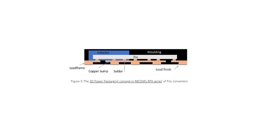
For example, if the PoL converter is over-molded, lead frames can be utilized rather than fiberglass circuit boards, with land grid array-style surface-mount terminations for a better packing factor and enhanced thermal performance. Inductors can be incorporated in the molding, over the lead frame, for better utilization of the ‘Z’ dimension.
3D Power Packaging concept
RECOM is a pioneer of these techniques with its ‘3D Power Packaging’ concept. A good example is their RPX series (Figure 3), which has a ‘Flip Chip on Leadframe’ construction.
A 1.5A version supplies a programmable 0.8–24V output from 4 to 36V input in a QFN package, 3mm x 5mm footprint, and 1.6mm high.
Re-Distribution Layer
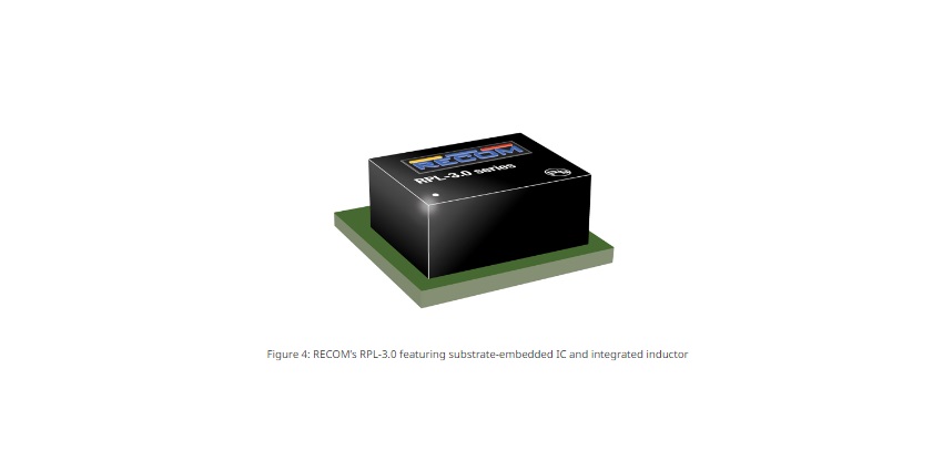
Where a conventional substrate is used, the PoL control IC can be embedded within the PCB layers for space-saving, as in RECOM’s RPL-3.0 series (Figure 4). The die is essentially bare, with an additional metalized Re-Distribution Layer which allows direct contact between the silicon and the internal PCB copper tracks.
The SMT inductor, capacitors, and other passive components are conventionally fitted onto the top of the substrate, and connections are made to the application PCB via gold-plated pads on the bottom. The result is a part able to supply more than 15W output from a wide input range of 4V to 18V, in a footprint of just 3mm x 3mm and 1.45mm high.
RPM, RPMB, and RPMH series
Along with six-sided metallic shielding, this thermally enhanced arrangement allows full power operation
Other parts, such as the RECOM RPM, RPMB, and RPMH series in 25-pad LGA packages, achieve their high power density by utilizing an internal multilayer PCB with plugged and blind vias.
Along with six-sided metallic shielding, this thermally enhanced arrangement allows full power operation up to higher than 85°C ambient temperature.
bonus effect
The reduced height and footprint of these new generations of module PoL converters open up the possibility of fitting them on the ‘back side’ of a motherboard, directly under the processor, or even co-packaging them with a complex IC.
The miniaturization also has a bonus effect in that EMI-generating loops within the converter are kept very small, therefore emissions are also very low, helping to reduce the need for additional filtering and further freeing up board space.
A range of power modules is needed for all applications
The input to a power module may be derived from a regulated bus at 12V, 5V, 3.3V
Point-of-load converter modules do not have standard input ranges, and outputs needed could range from around 0.5V to 3.3V or possibly to 5V for legacy designs. Current ratings could also vary from sub-one amp to tens of amps.
The input to a power module may be derived from a regulated bus at 12V, 5V, 3.3V, or sometimes an intermediate value such as 9V. Increasingly, for battery-powered devices the input could be from a lithium-ion cell at around 3.7V but could be over 4V when charging and 3V or less when heavily discharged.
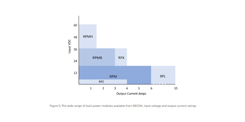
RP and RB series
Equally, the input may come from an unregulated source and vary over a 2:1 range or more. To meet a wide range of applications, RECOM offers parts in their RP and RB series with inputs down to 0.85V for a boost converter and up to 65V for a buck converter.
All parts have adjustable outputs and cover applications needing outputs of anything from 0.6V to 35V. Current ratings are from 0.5A to 15A. Figure 5 summarizes the buck converter combinations available.
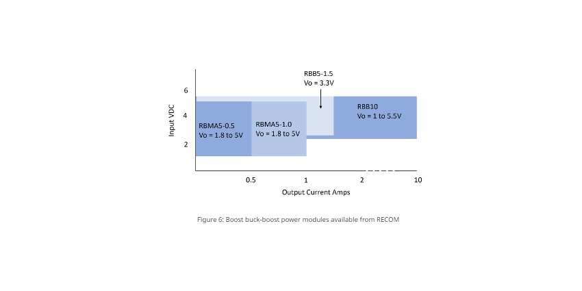
boost power modules
Figure 6 similarly shows the range of boost power modules available from RECOM with up to 10A rating.
The RBB5-1.5 and RBB10 parts are buck-boost types where the output can be higher or lower than the input, which is useful for maintaining regulated power from a battery source as it discharges.
Buck and boost converters
All buck and boost converters additionally have over-temperature and output overcurrent protection
Boost converters offered up to 1.5A include output overvoltage protection, and all include a true load disconnect function when disabled, which is necessary as there is usually a direct DC path through a boost converter when not switching.
All buck and boost converters additionally have over-temperature and output overcurrent protection.
Moore’s Law applied to PoL converters?
So, have power modules caught up with Moore’s Law? Let’s take a couple of examples comparing PoL converters with 24V input and 3.3V output at 4A. Just four years ago, in 2018, a part was advertised as ‘pioneering the advancement of power conversion’. It had a footprint of 33mm x 13.6mm, it was 8.8mm high, and had a volume of 3950 mm3.
RECOM RPX-4.0 has a 5mm x 5.5mm footprint, is 4.1mm high, and has a volume of 113 mm3, with a 35-fold increase in power density. Interestingly, the efficiency of the two parts is about the same, the improvement all down to higher switching frequency with smaller components and 3D power packaging techniques.
The value proposition of power modules is clear
Power modules using 3D power packaging simply cannot be replicated economically
With older open-frame DIP-style technology PoL converters, it was often evident to users that the same components could be fitted on their motherboard, making the value of a bought-in module questionable. Even space-saving SIP parts could easily be replicated by the user to save costs, using the same component styles and assembly technology that they were already using on their motherboards.
However, power modules using 3D power packaging simply cannot be replicated economically in motherboard fabrication technology, and the modules can be regarded as components such as resistors or capacitors that users would never think of fabricating themselves. The size of power modules enables them to be fitted easily around or under other components, and highly automated manufacturing techniques are used to drive costs down and reliability up.
Conclusion
Power modules offer power density performance that far exceeds what is possible with discrete solutions. Gains in recent years have rivaled those in IC transistor density, in line with Moore’s Law.
With manufacturing automation, costs are increasingly competitive, and when purchasing, stocking, placement, and test overheads are factored in, a module solution easily comes out on top. The extended range available from RECOM covers all common power and voltage levels found in applications from hand-held devices through to server and telecom boards.