Jenkins Electric Company - Experts & Thought Leaders
Latest Jenkins Electric Company news & announcements
A generator is a machine that converts mechanical power to electrical power, either AC or DC. The mechanical power can be provided by several different sources; such as a diesel or gasoline engine, water wheel, windmill, or electric motor. An alternator is a specific type of generator that converts mechanical power to AC electrical power. We will be focusing on alternators in this paper. Excitation methods There are different options for excitation methods. First is a self-excited system. The output from the alternator provides the power for the Automatic Voltage Regulator (AVR) as well as the sensing voltage to the regulator. The auxiliary winding is a separate single-phase winding that is inserted into the main stator The second form of excitation is the separately excited method using a permanent magnet generator (PMG). This configuration has a small PMG mounted on the non-drive end that supplies power for the AVR. The main generator output still supplies the sensing voltage. Another form of excitation uses an Auxiliary Winding. The auxiliary winding is a separate single-phase winding that is inserted into the main stator in the same slots as the main output winding. How does it work? In the case of the PMG method of excitation, the PMG rotor produces a high-frequency AC voltage in the PMG stator which the AVR uses to supply DC to the exciter fields. This generates three-phase ac power in the exciter rotor which is rectified and fed into the main rotating fields. The main DC fields generate AC output from the main stator which provides feedback to the AVR. Using the PMG allows the AVR excitation to remain at full capacity when sudden loads are applied to the generator, giving better motor starting performance. Component Characteristics and Testing If the user needs to rewind the exciter rotor it must have the same number of poles as the exciter fields The number of exciter poles is normally more than the main generator poles. This provides a higher frequency that when rectified gives a cleaner DC. The exciter fields are DC fields and can be voltage-dropped just like a field in a DC motor. If the user needs to rewind the exciter rotor it must have the same number of poles as the exciter fields. Diode bridge The diode bridge has a positive rectifier plate and a negative rectifier plate. There is usually a suppressor across the rectifier plates that protects the diodes as well as the main stator. A multimeter will read between 0.4 and 0.7 volts on the diode scale with the positive lead on the anode and negative lead on the cathode. If the user swaps the leads it will read open. If it reads open in both directions or shorted in both directions then the diode needs to be replaced. Multimeter measurements If the output from the PMG is too low then either the PMG is weak or there is a fault The best way to test the PMG is while it is in service on the generator. Find the tag on the AVR to find the sensing voltage required and the required PMG output. With a multimeter measure these voltages to verify that they are within range. If the output from the PMG is too low then either the PMG is weak or there is a fault in the PMG stator. Controlled DC supply A variac with both a rectified DC output and AC output is a very useful tool in testing a generator. It can be used to voltage drop the main rotor and the exciter fields with the controlled AC supply. The controlled DC supply can be used to bypass the AVR and separately excite the exciter field. While applying DC directly to the exciter field of an unloaded generator user can measure the required DC input voltage and current to generate full voltage. This can be useful in sourcing an aftermarket AVR. DC voltmeter Adjust the pot to dim and brighten the bulb, return the pot to the original output voltage A resistive load, such as an incandescent light bulb, is required to test the AVR. Connect the light bulb to the F+/F- of the AVR. Apply the required supply voltage and sensing voltage to the AVR. Use a DC voltmeter to measure the output across F+ and F. Adjust the pot to dim and brighten the bulb. Return the pot to the original output voltage. If the user Has to Rewind the Generator Component Characteristics and Testing Before burnout, identify the leads. If there are leads other than output power leads, they may be taps or auxiliary windings to provide voltage for the AVR. If there are taps or auxiliary windings present it is best to burn out the stator without cutting the coil end. Auxiliary windings The main winding acts as the primary of a transformer and the auxiliary winding acts as the secondary There can be more than one auxiliary winding. Some manufacturers use a single-phase transformer auxiliary winding and a load-dependent booster winding. For the auxiliary windings, it is all about location, location, and location just like in real estate. Mark a slot as #1, the main lead #1 is a good reference. Draw a diagram of the auxiliary windings about the marked slot. Insert the main windings and auxiliary windings in the same slots. The main winding acts as the primary of a transformer and the auxiliary winding acts as the secondary. If the coils are not placed back in the same orientation, they may have incorrect voltage supplied to the AVR. Original winding data When there are taps, count the number of coils to the main lead and the non-output lead. A tap may be within a coil so count the number of turns to the tap. It is best to maintain the original winding data. It is common for a manufacturer to use a 2/3 pitch to eliminate third harmonics in the output. Always verify that the number of poles in the main stator matches the number of poles in the main rotor.
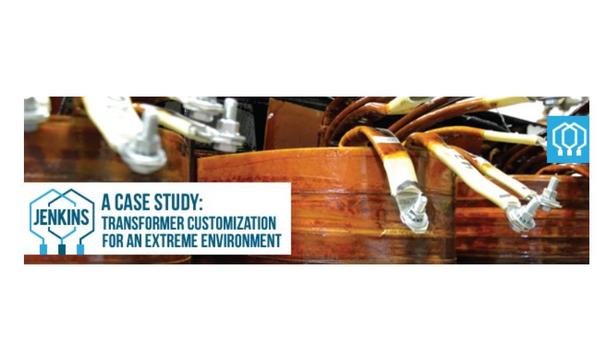
Jenkins sold a Jenkins Motor Test System to Oman, where temperatures can exceed 120ºF. While Jenkins Motor Test Systems are built tough and for industrial environments, this specific location required customizations to be the most effective in an extremely hot environment. Locations near large bodies of water or tropical environments can also cause problems as the humidity in the air will cause the copper wiring in the transformer to oxidize over time. Although Jenkins designs its equipment to operate for long periods, some applications for customer environments require specific customization. The Solution Jenkins engineers and winders worked together to develop a custom solution for this harsh climate, particularly paying close attention to temperature and water resistance. To customize the transformer for this environment, the Jenkins team made the following modifications: Doubling the spacing between winding layers to increase airflow. Encasing the transformer first in a high tolerance epoxy varnish, and then in a polyester over-dip that prevents the application from rust, dust, and harmful materials. Utilizing expanded metal at the base of the MTS enclosure, allows heat to escape, reducing the internal temperature. Installing temperature-sensitive cooling fans (set to 100ºF) atop the enclosure to prevent overheating. The Results Jenkins technicians checked insulation for 10,000 volts (resistance to ground), checked each voltage leg, and high voltage potential to ground, and ensured the taps were in the correct place. Voltage was confirmed to operate up to 20% above normal operation, ensuring maximum efficiency and longevity of the transformer. These modifications have resulted in prolonged use of the Jenkins Motor Test System in harsh environments and ultimately customer satisfaction.
Jenkins Electric, an electromechanical service and parts provider, specializing in electric motor repair and test products, as well as a variety of distribution parts, has acquired Wheeler, a sleeve and fluid film-bearing manufacturer based in North Charleston, South Carolina, USA. “This acquisition expands our capabilities and offerings in the industrial motor parts and service industry,” said Iain Jenkins, Jenkins President, adding “From the North Charleston location, Jenkins will continue the Wheeler tradition of precision manufacturing. We've built a company and culture that we're proud of and retaining the technical and customer service team at Wheeler only enhances our offering and dedication to customer success.” Variety of OEM customers In addition to offering rebabbitting services on motor, turbine, fan, and gearbox bearings Wheeler Bearing Company serves a variety of OEM customers around the world. With deep experience and strict adherence to ISO-certified manufacturing practices, Wheeler manufactures babbitt-lined bearings, aluminum alloy bearings, and labyrinth seals. In addition to offering rebabbitting services on motor, turbine, fan, and gearbox bearings. With a commitment to meeting deadlines, exceeding quality expectations and expanding the ability to serve customers, Wheeler Bearing Company, Powered by Jenkins will be led by General Manager, Ryan Ossmann. The experienced technical and customer service team, formerly of Wheeler Industries, will remain in North Charleston under Ryan’s leadership. Expands the distribution business This acquisition further expands the distribution business offered by Jenkins, which now includes sleeve and fluid film bearings, motor cooling fans, winding protection, and motor parts in addition to serving as the exclusive US distributor of Axalta resin. “Jenkins has a long history of being a locally owned family business with a dedication to supporting fellow motor shops across the Southeast and the entire country. One of the ways we continue to lend support is by offering same-day shipping and no minimums on the critical replacement parts we know other shops rely on daily. If it’s available in our online store, it’s been Jenkins tested and approved,” stated Iain Jenkins.


